
 Menu
MenuStrand7 Software: Case Studies: Catamaran
Analysis of an 80m high-speed catamaran in accordance with Det-Norske Veritas' rules for high-speed light craft |
Background |
| Strand7 Consulting used Strand7 to perform a global strength analysis on an 80m high-speed catamaran vehicular ferry in accordance with Det Norske Veritas' Rules for High-Speed Light Craft (HSLC). |
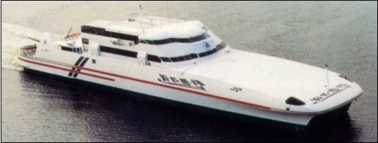 |
The classification society Det Norske Veritas Classification AS (DNV) requires that a complete three dimensional global strength analysis be performed on high-speed catamaran vehicular ferries more than 50m in length. The overall length of the K50 class vessel is 80.1m. The vessel is powered by four Ruston 16RK 270 diesel engines, each rated at 5,500 kW, and using a propulsion system consisting of four steerable KaMeWa 80 waterjets. This gives a service speed of 47 knots and a sprint speed of 53 knots. The main deck is configured for up to 89 vehicles. The aft deck is capable of carrying large heavy vehicles such as buses or fast freight. The second deck accommodates up to 400 passengers with all essential services. |
Scope of WorkThe analysis assessed the structural behaviour of the vessel subjected to seven DNV global HSLC load cases. |
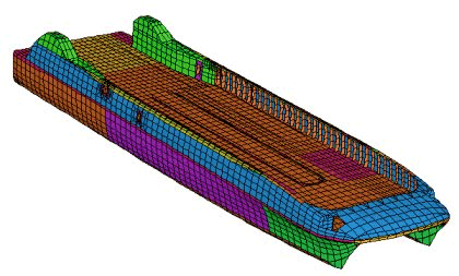
A finite element model of the starboard side of the vessel was prepared to reflect the hull lines and details shown in the general arrangement and structural scantling drawings. The starboard side model below was then mirrored to produce the global finite element model of the vessel. |

|
The super-structure is mounted on rubber resilient mounts and was not included in the analysis. The reaction loads of the super-structure acting on the super-structure mount landing angle were included in the analysis. |
The four node Thin Shell element was used to model the plating of the vessel (i.e. hulls, decking, bulwarks, transverse bulkheads, frames, antechambers, etc). Beam elements were used to model the riders, stiffeners, pillars, etc. |
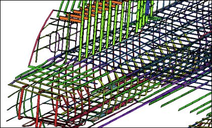
The size, type and number of elements were carefully selected to ensure the effects of bending, shear and torsion of the hull beam were fully accounted for in the analysis. The mesh grading used was based on the spacing of both the frames and the longitudinal stiffeners. |
|
The node lines of the finite element model coincided with all chines as well as actual stiffener positions on the hulls and bulwarks. Inertia correction techniques were therefore used to lump stiffener areas to the beam elements on the plate element node lines. |
The layout of the finite element mesh was designed so that stiffeners either side of the node line could be lumped to the stiffener on the node line. This inertia lumping technique involved the addition of the areas of the adjacent stiffeners to the area of the beam element on the node line representing the stiffener. |
|
Statistics |
| Nodes | : | 10179 |
| Beams | : | 8625 |
| Plates | : | 12781 |
| No of Equations | : | 60990 |
AnalysisThe HSLC load cases inherently produce in-plane longitudinal bending. In the Linear Static Solver, there is a requirement that the boundary freedom conditions be sufficient to prevent rigid body motion, and therefore, the model must be restrained in this plane to prevent translation and rotation. In doing so, however, the artificial restraint applied to the model (requiring a great deal of assumption) may influence the natural flexural behaviour of the vessel. |
One technique commonly used to restrict rigid body motion and allow some degree of flexibility in the vessel is the use of spring type elements. These elements restrain the model sufficiently to restrict rigid body motion, and at the same time allow the solution to approximate the degree of flexibility in the bending plane. The spring elements are checked to verify that they do not carry significant load. |
On the other hand, the Transient Dynamic Solver does not require freedom conditions to restrict rigid body motion (only that the forces be in equilibrium). Therefore, this solver eliminates the need to apply artificial restraints to the model to prevent rigid body motion, and thus allows the natural flexural behaviour of the vessel to be modelled. |
The solution method used was the Newmark-Beta method with Rayleigh damping. The first, second and third natural frequencies predicted by the Natural Frequency Solver were used. The damping ratios corresponding to upper and lower frequencies were both set to near critical damping (i.e. z = 0.999). |
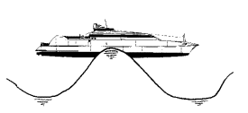
Sagging Moment |
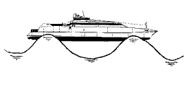 |
| The sagging moment load case may be the critical load case with respect to the allowable longitudinal stresses and the buckling capacity of the upper section of the bulwark. This load case may generate large longitudinal compressive stresses in the bulwark top plate and large tensile stresses in the keel plate. |
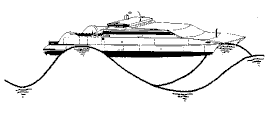
| Hogging Moment |
 |
| The hogging moment load case may be the critical load case with respect to the allowable longitudinal stresses and the buckling capacity of the lower section of the hull. This load case may generate large longitudinal compressive stresses in the keel plate and tensile stresses in the bulwark top plate. |
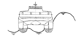
| Transverse Split Force |
| The transverse split force load case may be the critical load case with respect to the allowable transverse and shear stresses, as well as the buckling capacity of the structure between the hulls, the sides and bulkheads. This load case may generate large transverse compressive stresses in the main vehicle deck and tensile stresses in the wet deck. Large shear stresses may also be induced in the transverse bulkheads. |
| Pitch Connecting Moment |
 |
| The pitch connecting moment load case may be the critical load case with respect to the allowable stresses and the buckling capacity of various plate panels, stiffeners and beams in the cross structure. |
| Transverse Racking |
 |
| The transverse racking load case may be the critical load case with respect to the allowable transverse stresses and the buckling capacity in the lower side frames and transverse bulkheads. |
|
Combined Load Cases The combined load cases may be the critical load case with respect to the allowable longitudinal stresses and the buckling capacity of the mid-ship section. |
ResultsThe results of the global strength analysis were evaluated with respect to allowable global stresses and the buckling capacity of various plate panels, stiffeners and girder systems. |
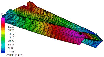 |
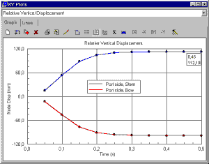
The output results were checked for plausibility of deformation, overall stress magnitudes, and local stress concentrations. Graphs of the vertical displacement of a control node were plotted against each time step and evaluated to check that the Transient Dynamics solver reached a steady state solution. |
 |
|
For more information on marine applications, see Strand7 Webnotes - Applications / Marine. |