
 Menu
MenuStrand7 Software: Case Studies: Girder
Fatigue assessment of runway girder for coke transfer cars at BHP, Port Kembla |
Introduction |
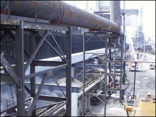
| Strand7 Consulting used Strand7 to analyse the runway girder for the Coke Transfer Cars of the Coke Oven Batteries at the BHP Steel Works, Port Kembla, NSW, Australia. The runway girder is part of the Rail and Support Duct Structure for the Coke Side Emission Control System. The work is part of BHP's environmental project for a cleaner environment for Port Kembla. |
|
|
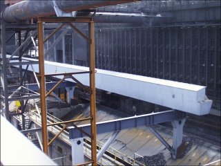
The runway girder supports the crane rail along which the coke transfer cars travel, servicing the coke oven batteries. The coke transfer cars travel at a maximum speed of 1 m/s. The girder has an overall depth of 2,000 mm and an overall width of 950 mm. The top and bottom flanges of the girder are typically fabricated from 50 mm plate and the webs are typically 16 mm and 32 mm plate. The overall length of the runway girder is 431.79 m and consists of individual girder lengths which rest on trestles. Each girder has a camber of typically 6 mm. |
|
The crane rail rests on 155 CT 79 sections which are fabricated into the girder web by continuous longitudinal butt welds. This section has a nominal web thickness of 15.7 mm but was analysed as 13.5 mm to allow for possible corrosion over the full design life of the girder. |
|
The project has a capital value of AUD93 million. |
Scope of Work |
| The principal aim of the analysis was to evaluate the overall stresses in the girder overhang and to perform a fatigue assessment on critical weld details. An important part of the FEA brief was to focus on the overhang sections of the unique girder design. In particular, the longitudinal complete penetration butt weld between the 155 CT 79 web and girder web plating was investigated for the possibility of fatigue cracking induced by the four 50 tonne wheel loads of each coke transfer car. |
2D analysis |
| A two dimensional analysis using beam elements was used to find the critical section of runway girder to be analysed. Nodal forces representing the wheel loads at different points in time were studied to establish the extreme design values of bending moment and shear force. Strand7's load case envelope generator was used to visualize the moment and force diagrams along the beam as the car travels its length. |
|
|
Strand7's arbitrary section generator was used to determine the section properties of the girder, for modelling as a 2D beam. The figure shows the Strand7 rendering of a beam element. |
|
3D analysis |
| A three dimensional finite element model of the critical runway girder was later prepared using a combination of beam and spring elements, thin shell plate elements and brick elements. The size, type and number of elements were carefully selected to ensure the effects of bending, shear and torsion of the girder were fully accounted for in the analysis. In general, the mesh grading resulted in the plate elements being virtually square (i.e. an aspect ratio of approximately one), particularly where stresses were to be recovered. The mesh around cope holes, radii, etc, was refined to evaluate stress concentrations. |
|
|
The 86 kg BHP crane rail and gantrail adjustable clips were modelled using the 8 node brick element to allow the correct load path of the wheel loads into the girder to be applied. The Fabreeka SA47 Crane Rail Pad and the vulcanized rubber on the clip were modelled using coil spring elements. Contact surfaces were also modelled using spring elements. |
|
Statistics |
| Nodes | : | 19521 |
| Beams | : | 1121 |
| Plates | : | 12671 |
| Bricks | : | 4968 |
| No of Equations | : | 97112 |
Analysis |
| Since the coke transfer cars travel at a maximum speed of 1 m/s, the Linear Static Solver was considered appropriate to analyse the runway girder. The reactions at the fixed nodes were recovered. This allowed the overall equilibrium of the structure to be checked. |
|
Load cases such as dead load (i.e. gravity), live load (i.e. wheel loads), wheel eccentricity and oblique travelling forces and combinations of these loads were analysed. In general the wheel loads were applied as brick surface pressures on top of the rail. The maximum bending moment was applied to the bearing plate as plate surface pressures. Each load case represented a particular position of the coke transfer car in time. |
|
|
The design loads were based on an upper bound estimate of the accumulated service conditions over the full design life of the structure (i.e. account was taken of all likely operational and environmental effects arising from the foreseeable usage of the runway girder during the life of the gantry). As such, and in accordance with the standards, the loads were not factored for the fatigue assessment. The extreme design values of bending moment and shear force were applied to the model. |
|
The stress distributions shown are based on the stresses averaged by plate element property type. This averaging technique gives the most accurate picture of the true stress distribution in the real structure. It also accounts for apparent stress discontinuity in the contour plots. |
Fatigue assessment |
| The fatigue assessment was carried out in accordance with Section 11 of AS 4100-1990 and BS 7608:1993, "Code of Practice for Fatigue Design and Assessment of Steel Structures". |
|
The design stress ranges include the normal and shear stresses taking into account all design actions on the member (i.e. bending and reaction forces). Principal stresses were used when the normal and shear stresses occur simultaneously. If the normal and shear stress ranges do not occur simultaneously at the same location, the components of damage were added using Miner's rule. |
|
|
The relevant stress range used in the fatigue assessment was taken as the maximum Gauss point stress value on the surface of the plate element adjacent to the potential crack location in the weld detail and not at the detail itself. This is considered appropriate since the detail category already takes into consideration the local stress concentration at the detail, the size and shape of the maximum acceptable discontinuity, the loading condition, metallurgical effects, residual stresses, the welding process and any post weld improvement. |