Strand7 Software: In Detail: Moving Load: Load Influences
Moving load capabilities
| The Strand7 moving load module allows detailed specification and analysis of moving loads along prescribed load paths. The moving load module (a combination of a Load Path and a Load Path Template), combined with the load influence solver or one of the time-dependent solvers, offers a highly effective means of performing moving load analysis. | |
Load InfluencesLoad Influence SolverThe basis of the moving load module in Strand7 is the Load Influence solver. This solver is used to determine influence lines and influence surfaces. In other words, you can determine the effect that a unit load (force or moment) will have on a particular response variable at a node or element. For example, you are modelling a doubler plate, where minimising the centre deflection is of importance. You would assign a vertical displacement response variable to the centre node and run the Load Influence solver. The results will allow you to determine the loading location that generates the largest centre deflection. | |
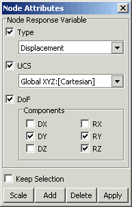
Response Variables There are a number of response variables that can be assigned to the different element types in Strand7. For nodes you can specify displacement or reaction, in a UCS or the global Cartesian system. For beams you can specify axial and shear force, bending moments and torque. For plates you can specify forces and moments, and for bricks you can specify stresses. Any number of response variables can be solved with each run of the solver - effectively each response variable generates a pseudo load case for the solver. | |
| |
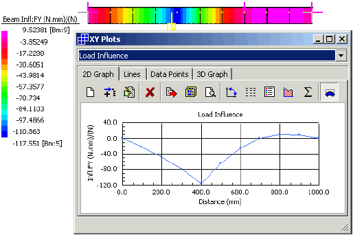
Influence Line and Surface For example, a simply supported beam is assigned a bending moment response variable as indicated. The results show that a vertical unit force applied near the point of interest will give a bending moment of -117.551 Nmm at the location of the response variable. Alternatively a unit force applied near the right hand end will give a bending moment of 9.524 Nmm at the response variable location. | |
| |
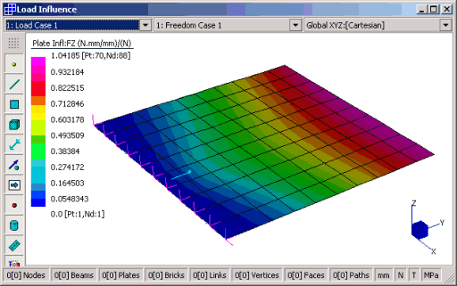
Similarly, the Influence Surface is plotted as a contour. For example, the following Influence Surface indicates that if a unit Z force is applied near the free edge of the plate, the bending moment at the selected response variable plate will be at its maximum, with an approximate value of 1.04185 Nmm/mm. | |
| |
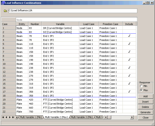
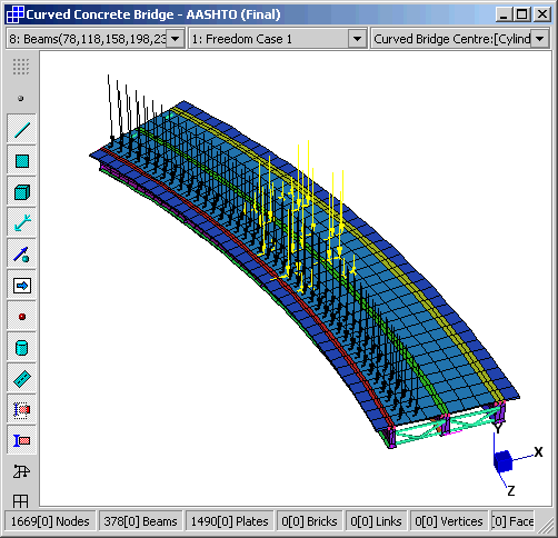
Load Influence Combination Load Paths can be combined with response variables to generate Load Influence Combinations. This will automatically determine and create the critical load combination cases based on the included variables, the type of response and the vehicle configurations. | |
| |
Load Influence Combinations can be either Single Variables or Multi Variables, depending on whether you require the Max and Min response of individual response variables, or combinations of them. For example, you can find the load combination to generate the maximum reaction at a single node, or the load combination to generate the maximum reaction sum at multiple nodes. Once generated, new load cases will be created in the model that correspond to the load influence combinations that apply the critical load to the model. These additional load cases are treated as normal load cases and therefore may be combined with other loads. | |
| |
|
For more information on moving load applications, see Strand7 Webnotes - Applications / Bridges. | |

 Menu
Menu