
 Menu
MenuStrand7 Software: Case Studies: Thickener
Analysis of a drive unit for a Skorpion Zinc Mill Thickener |
Introduction |
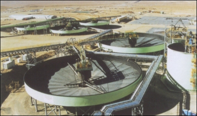
| Strand7 Consulting were contracted to complete an analysis of a drive assembly for Outokumpu. Outokumpu design and manufacture thickeners and clarifiers that are used in mineral processing, effluent applications, chemical and water treatment. The job was to model a drive unit for one of their latest high torque designs to investigate deflections and stresses. |
|
| An example of a large thickener with the drive unit at the centre |
The structure analysed |
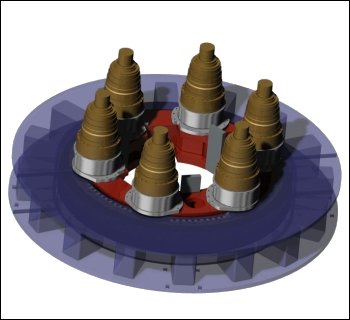
| The drive unit consists of the base supporting structure, hydraulic motor mounts, pinion gears, slew ring gear, cage adapter ring and cage structure. Six motors are used to provide the drive action. For the analysis Outokumpu provided a Solidworks model of the gearbox assembly that was imported into Strand7 and used as the basis for the mesh construction. Strand7 Consulting employed a combination of automatic surface meshing and manual brick extrusion techniques within Strand7 to generate a model made up of beam, plate and brick elements. |
|
| CAD Model of the drive unit |
Exploiting Hex Extrusion |
|
In many cases, a solid CAD geometry is created by extruding one or more surfaces in a straight line or about an axis of rotation. This same extrusion technique can be exploited in Strand7 and such models can be generated without the solid automeshing tool. That is, it is possible to replicate the process in the FEA model by first generating a surface mesh and then extruding this mesh into a solid mesh that completely fills the intended solid geometry. By following this procedure, it is possible to create a hexahedral or "hexahedral dominant" solid mesh of better quality than a solid automeshed tetrahedral mesh. This can be done using these simple steps: |
|
| 1. Identify in the CAD model the base surfaces for extrusion |
|
| 2. Define a split line and split the base surface into two separate but compatible surfaces |
|
| 3. Import the CAD model into Strand7, surface mesh the two base surfaces then extrude in layers to create a hexahedral mesh. |
Model Building |
| By using the meshing tools in Strand7, the entire drive unit assembly was created, using beams, plates and bricks. Special connection links were used to simulate the drive mechanism. |
|
| Complete model, showing drive assembly and cage structure |
|
| Pinion to gear connection by stiff beams and master slave links |
Scope of work |
| The purpose of the analysis was primarily to investigate the out of plane deflections of the slew ring and the deflections of the pinion drive shaft under the design torque. Additionally the stress levels in the primary structural elements were also investigated. |
|
Four linear Static Load Cases were run: |
| 1. Gravity |
| 2. Torque |
| 3. Face Shear on Keyway Bearing Surfaces |
| 4. Vertical Load from rake arms |
Results |
| The analysis confirmed the design was within the deflection limits of the slew ring gear used and that the structure was within the stress limits of the material used. |
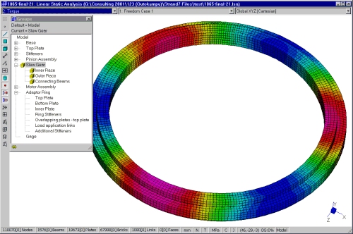
|
| Slew Ring Deflection Plot |
|
| Animation showing relative rotation of components under load |