
 Menu
Menu| << Previous (Applications) | (Theory) Next >> |
ST7-R3.50 Modelling |
||
|---|---|---|
| ST7-R3.50.10 Modelling / Automeshing | ||
 1.2 MB  |
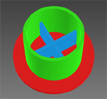
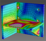
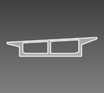
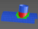
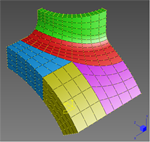
ST7-R3.50.10.1 Surface Automeshing Geometry and Hex Extrusion It is often optimal to use a combination of automeshing and manual meshing. This Webnote presents an example of a reinforced end detail of a steel pile, which is first surface-automeshed and then extruded into a solid hexahedral mesh. |
|
|
1.7 MB |
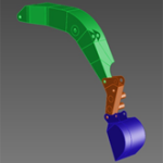
ST7-R3.50.10.2 Surface Automeshing an Excavator Assembly The Strand7 automeshing module enables you to rapidly mesh imported CAD geometry. The geometry tools in Strand7 allow you to split and heal geometry to prepare it for automeshing when the initial imported geometry is lacking sufficient definition for FEA purposes. The Webnote covers:
|
|
|
1.6 MB |
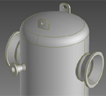
ST7-R3.50.10.5 Reducing Solid Geometry to Surfaces for Plate Meshing This Webnote demonstrates tools and techniques within Strand7 that can be used to produce geometry suitable for plate meshing from solid CAD geometry. These are suitable when the CAD file consists of a single body incorporating all the features of a relatively thin structure or component. In the case where the CAD file identifies different components, or thin parts, via different groups, the conversion of solids to mid-plane representation is usually more efficient by using the Mid-plane Thin Solids tool. |
|
|
3.6 MB |
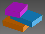
ST7-R3.50.10.6 Solid Automeshing Multiple Connected Bodies In solid automeshing it is common to have geometry that shares an interface with another part to which it is connected. Examples include bonded structure, adjacent parts, and changes in material properties within a solid object. This Webnote outlines how to produce compatible meshes at the interface between multiple regions in a solid mesh. It is assumed that the geometry includes faces at the interface between the bodies. Two methods of creating compatible meshes are covered, depending on the form of the geometry. A third method attaches multiple incompatible meshes using attachment links. |
|
|
0.9 MB |
ST7-R3.50.10.7 Generating Geometry in Strand7 Strand7 offers a range of tools to help create and manipulate geometry in preparation for automeshing. Although these tools are not intended as an alternative to a CAD package, they offer sufficient functionality to generate various basic geometries from scratch, and more importantly, to make additions and modifications to imported CAD geometry – this can often avoid the need to go back to the CAD package to correct unmeshable geometry. |
|
|
1.2 MB |
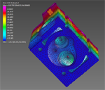
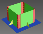
ST7-R3.50.10.9 Geometry Creation of a Cast-in Bearing Plate Bracket This Webnote outlines a procedure for modelling a welded steel bracket and bearing plate assembly, subjected to a 300 kN load. The bracket is cast into an adjacent concrete member using six N24 reinforcing bars welded to the back of the bracket. The modelling is performed within Strand7, without the aid of CAD software. |
|
|
1.5 MB |
ST7-R3.50.10.16 Overview of Geometry Tools The geometry importer, geometry tools and automeshing tools in Strand7 make it possible to convert CAD geometry into an FEA model. This Webnote focuses on the geometry tools and how they can be used to process geometry imported from a CAD file to make it suitable for automeshing. |
|
|
5.8 MB |
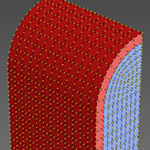
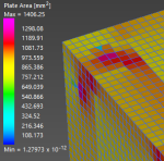
ST7-R3.50.10.20 Checking and Correcting Brick Faces The quality of the surface of a brick mesh can be assessed by creating plate elements on the brick surface. These plates can then be measured and inspected. They can also be left in the model for analysis if their properties are set such that they do not influence the solution (e.g., by setting their modulus and/or thickness to very small values). |
|
|
0.6 MB |
ST7-R3.50.10.25 Using DXF Imports for Automeshing DXF is a CAD file format originally used for 2D and 3D sketches represented by polylines. In recent years, ACIS SAT geometry data has been incorporated into DXF files (ACIS SAT files offer greater flexibility to represent 2D and 3D surface and solid geometry). Strand7 can import both types of data contained in DXF files: polylines and SAT geometry. This Webnote examines the import of these types of data from DXF files, together with procedures for preparing and meshing the underlying geometry. |
|
| ST7-R3.50.20 Modelling / Manual Meshing | ||
|
0.7 MB |
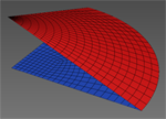
ST7-R3.50.20.1 Meshing a Conical Surface by Projection This Webnote shows how to create a high quality mesh of a cone by projecting a flat mesh to a conical surface. |
|
|
0.5 MB |
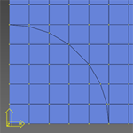
ST7-R3.50.20.2 Meshing a Plate with a Hole This Webnote presents a procedure that creates the mesh for a plate with a hole in it. A method for refining the mesh around the hole is also discussed. |
|
|
0.7 MB |
ST7-R3.50.20.3 Meshing a Solid Cylinder This Webnote provides an example of manual mesh generation. Strand7 meshing tools are used to create the mesh for a solid cylinder. Only a quarter of the cylinder is modelled due to symmetry. |
|
|
0.5 MB |
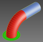
ST7-R3.50.20.4 Meshing a Pipe Elbow and Flange This Webnote outlines a procedure for creating a pipe with a 90° elbow using plate elements. This procedure could be adapted to model an elbow of any angle. It could also be adapted for use with beam or brick elements. |
|
|
0.7 MB |
ST7-R3.50.20.5 Intersecting Cylinders This Webnote presents a method for creating a plate mesh representing two intersecting cylindrical surfaces using manual meshing tools available in Strand7. |
|
|
1.7 MB |
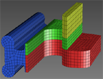
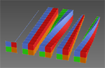
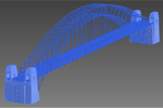
ST7-R3.50.20.6 Extrusion Meshing in Multiple Directions Some solid parts can be made from multiple extruded parts connected together. In these cases it may be preferable to create an extruded Hexa8 or Hexa20 mesh instead of a Tet10 automesh, because the number of nodes for a given accuracy may be greatly reduced when using hexahedral (extruded) brick elements. |
|
|
1.0 MB |
ST7-R3.50.20.7 Creating Cylindrical Features in an Existing Mesh This Webnote describes a method for creating features that have a circular or cylindrical shape. Typically, this can be achieved by performing mesh manipulation with reference to a Cylindrical UCS defined at an appropriate location. Some mesh adjustment may be required after a feature is added to the mesh to ensure mesh compatibility. |
|
|
0.7 MB |
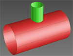
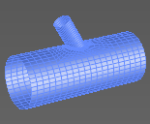
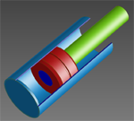
ST7-R3.50.20.8 Forming Compatible Mesh via Extrusion to Surface In many real structures, the intersection between two components is not defined by simple geometry such as straight or circular lines (for example, the intersection between two pipes is not easily described). This introduces some complexity into the modelling approach required to produce a compatible mesh when joining parts with different shapes. This Webnote illustrates the use of Strand7 tools to produce compatible mesh for the intersection between two pipes. |
|
|
0.5 MB |
ST7-R3.50.20.9 Modelling a Helix or Spiral Modelling a spiral in Strand7 can be done by using the Extrude by Increment tool with a cylindrical UCS. |

|
|
2.0 MB |
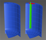
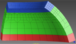
ST7-R3.50.20.10 Advanced Grading Techniques This Webnote examines manual mesh refinement techniques using the Grade Plates and Bricks tool. An important part of building a finite element model is mesh refinement around areas of stress concentration, changes in geometry and other areas of interest. The Grade Plates and Bricks tool can be used to define the transition from a coarse mesh to a fine mesh, whilst ensuring that all elements are fully connected and retain acceptable aspect ratios. |
|
|
4.8 MB |
ST7-R3.50.20.11 Creating Interface Elements between Coincident Geometry This Webnote illustrates operations and tools for creating interfaces between component parts, such as is required for the analysis of contacting bodies, or simply for disconnecting parts that have been zipped together. Although the physical parts may actually be coincident and may have been modelled in that way in a CAD program, for FEA purposes it is often necessary to introduce a small physical gap between the parts so that contact or other interface elements may be inserted. |
|
 0.6 MB |
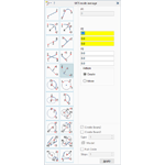
ST7-R3.50.20.14 Using the Nodes and Beams by Line Tool to Build Models This Webnote examines node and beam element creation using the Nodes and Beams by Line tools. Tools are available for creating nodes and beam elements on geometries such as parabolas and circular arcs, as well as on features like fillets and tangent lines. There are also tools to create construction features based on existing entities, such as finding the centre of a circular arc and extending existing lines. These tools are useful for both manual and automeshing approaches. |
|
|
1.5 MB |
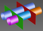
ST7-R3.50.20.16 Advanced Extrusion Meshing This Webnote examines the Strand7 extrusion tools, which are Extrude by Increment, Extrude by Direction, Extrude by Rotation, Extrude by Projection, Extrude by Thickness, Extrude by Line, and Extrude to Absolute. Some applications of the extrusion tools are presented together with relevant modelling tips. |
|
|
1.8 MB |
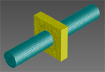
ST7-R3.50.20.18 Modelling Intersecting Pipes with Hexahedral Elements This Webnote illustrates techniques to manually create a mesh of intersecting pipes using 20-noded hexahedral brick elements. Tools such as extrude by projection, fillet plates and subdivide are used to produce the final mesh. |
|
| ST7-R3.50.50 Modelling / Details | ||
|
1.0 MB |
ST7-R3.50.50.23 Using Cavity Layout and Attribute The cavity attribute fills a closed cavity (i.e., volume) defined by plate and/or brick faces, with a fluid – e.g., the inside surface of a balloon, the inside surfaces of an IGU (Insulated Glass Unit), and so on. Two types of cavities are available and these are defined under LAYOUTS/Cavities:
|
|
| ST7-R3.50.70 Modelling / Attributes | ||
|
0.7 MB |
ST7-R3.50.70.9 Assigning Attributes to Geometry After importing CAD geometry, attributes can be applied directly to the geometry. These attributes are then automatically inherited by finite elements after automeshing. Advantages of applying attributes to geometry include:
|
|
| ST7-R3.50.80 Modelling / Model Manipulation | ||
|
0.3 MB |
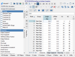
ST7-R3.50.80.1 Model Manipulation using the TEXT Tab The TEXT tab provides an efficient way to view and modify details of nodes, elements, links and paths via a text-based spreadsheet. As the information is presented in a grid, data can be readily copied and pasted to and from other applications via the clipboard. Data can also be edited directly in the grid or via a suite of tools and features designed to facilitate finite element data manipulation. This Webnote shows how a Strand7 model can be manipulated using the TEXT tab. |
|
|
0.3 MB |
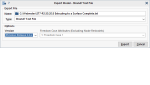
ST7-R3.50.80.3 Converting New Strand7 Models into Older Formats Every Strand7 release can open Strand7 models (i.e., .ST7 files) from all Strand7 releases that precede it; that is, there is backwards compatibility. However, older Strand7 releases cannot directly open .ST7 files saved by newer releases. This Webnote outlines how to export Strand7 models so that they can be imported into older Strand7 releases, and summarises some of the limitations. |
|
|
1.5 MB |
ST7-R3.50.80.6 Merging Two Models with Copy-Paste There are several ways to import one Strand7 model into another. The simplest and most powerful way is the Copy-Paste functionality. Entities in one model, the source model, are selected and copied to Strand7's internal clipboard. The target model is then opened and pasted into. There are options for what is to be pasted and where (including orientation and scale). |
|
|
1.1 MB |
ST7-R3.50.80.16 Removing Small-Area Plates using the TEXT Tab This Webnote illustrates a method for detecting and removing plate elements with very small area. This is also applicable to brick elements with very small volume, and to beam elements with very small length. The small area elements can be a by-product of automeshing, such as when the geometry contains very small faces, or Surface Automesh parameters that are unable to accommodate the meshing of elements over small geometric features. Small elements can also be created inadvertently through manual meshing operations with tools such as Move to Absolute or Cut Elements. If these elements are too small, they can have an impact on the local stress field due to numerical round-off or ill-conditioning. Therefore, they should be removed from the mesh prior to analysis and the mesh repaired accordingly. |
|
| << Previous (Applications) | (Theory) Next >> |