Strand7 Snippets
Snippet #4: Plate Thickness |

|
| Introduction | ||
|
The thickness of plate elements can be defined in the plate property data or via a plate element attribute. Thickness assigned as a plate element attribute supersedes the thickness in the plate property data.
|
||
| Property Thickness | ||
|
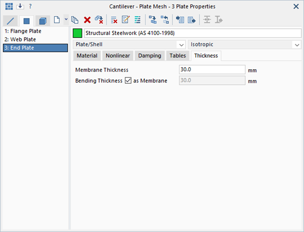
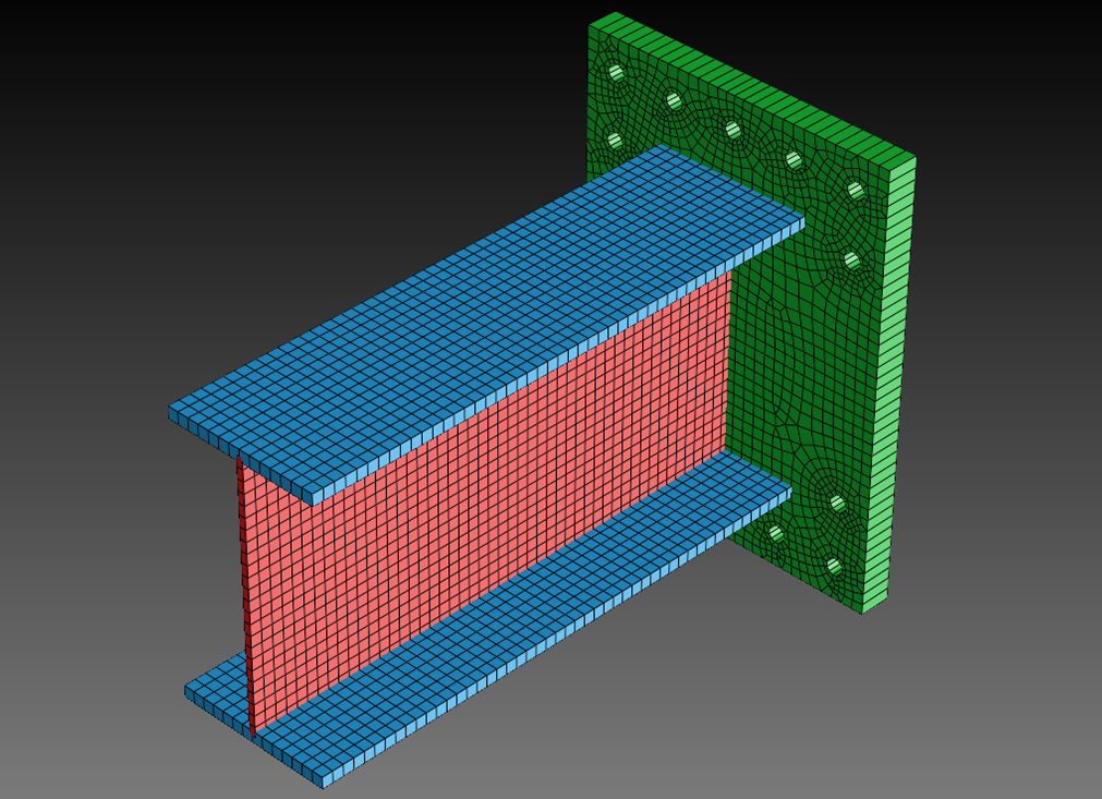
The default thickness of plate elements is defined in the plate property data (VISUAL/Global/Properties/Plate). In the dialog and mesh shown below, three different plate properties are defined – they all have the same material data but different thicknesses. The mesh is displayed according to the element property colour, with plate elements shown in the Solid style – the different plate thicknesses are clearly visible. |
||
|
|
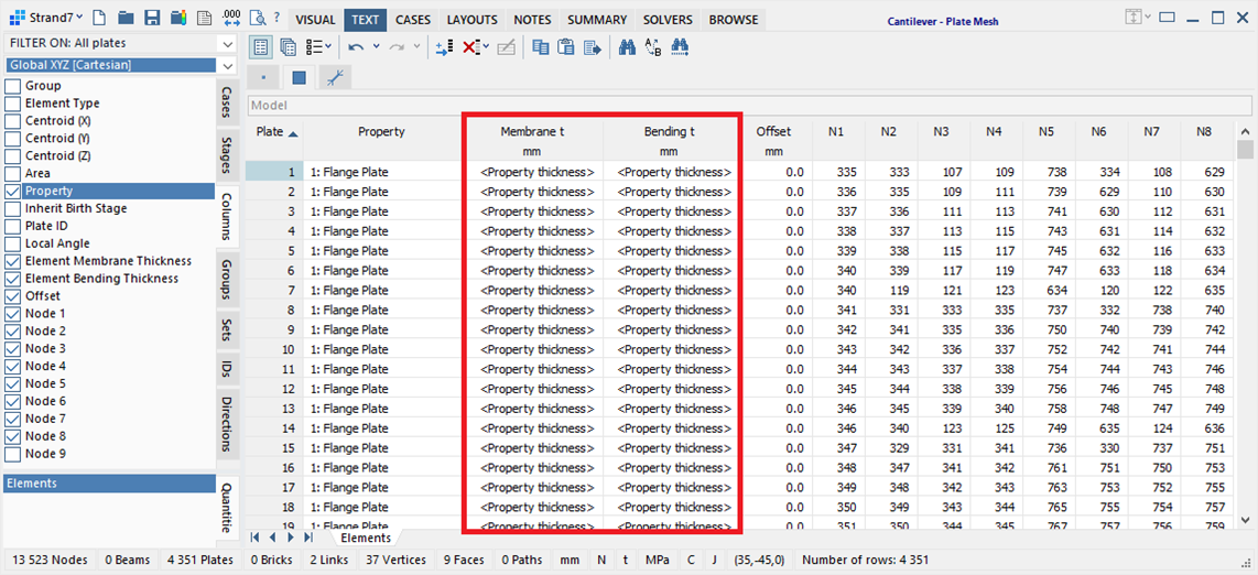
The TEXT tab confirms that the plate elements are using the property thickness by reporting membrane and bending thickness values in the grid as <Property thickness>. |
||
|
||
| Attribute Thickness | ||
|
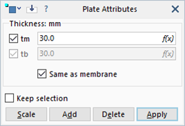
To override the property thickness, the Plate Thickness attribute can be assigned to individual plate elements (VISUAL/Attributes/Plate/Thickness). The property thickness is then ignored by the element and the plate property data only needs to define the material data; plate elements of different thickness can reference the same plate property data as long as they have a plate thickness attribute assigned. If there are many different thicknesses in the model, the use of the thickness attribute will simplify the model as it is not necessary to define a plate property for every thickness. |
|
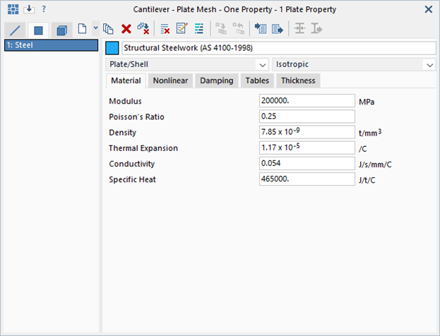
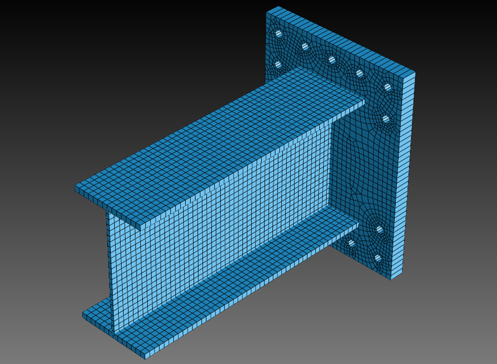
In the dialog and mesh shown below, only one plate property is defined – Steel. All plate elements reference this property, as can be verified by the plate property colour display (all elements are the same colour). Additionally, the different parts (flanges, web and end plate) have been assigned a plate thickness attribute – the thickness of each part can be verified by the solid style display. |
|
|
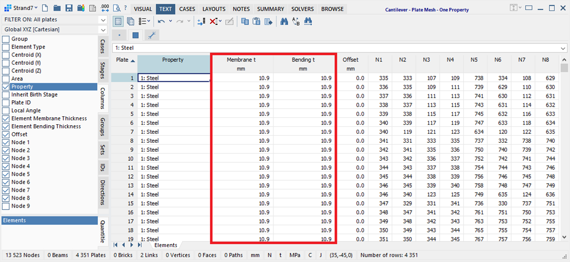
The TEXT tab now lists the membrane and bending thickness values according to the assigned attribute thickness. The thickness values can be changed here. |
||
|
||
| Additional Information | ||
|
To return a plate element back to the default property thickness, delete the plate thickness attribute via VISUAL/Attributes/Plate/Thickness, or set the values of membrane and/or bending thickness in the TEXT grid to zero.
The plate thickness attribute can be applied not only to plate elements, but also to geometry faces (VISUAL/Attributes/Face/Thickness); the automesher automatically transfers the face thickness to the plate elements. The geometry mid-planing tool (VISUAL/Tools/Geometry/Mid-plane Thin Solids) automatically assigns the thickness attribute to geometry faces extracted as mid-planes of thin solids (the thickness is calculated by the tool). This means that after mid-planing, it is not necessary to assign a thickness to the plate elements or to their corresponding plate property data. Linear plate/shell elements support two thickness values: membrane thickness, which is used to define the in-plane stiffness of the plate, and bending thickness, which is used to define the bending stiffness of the plate. This is useful for modelling corrugated or stiffened panels, and for modelling cracked concrete elements. |
||
|
|
||
|
|
||

 Menu
Menu