
 Menu
Menu| << Previous (Installation) |
ST7-1.70 Results |
||
|---|---|---|
| ST7-1.70.10 Results / Elements | ||
 0.5 MB |
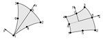
ST7-1.70.10.1 Moment Conventions in Plate Elements This Webnote describes the sign and direction conventions for bending moments in plate elements. Misinterpretation of results may occur without a clear understanding of the definitions of bending moments in a Strand7 model. When plate/shell elements are used in Strand7, the resultant moments at each element Gauss point are calculated by the solver. The solver determines three moments at each Gauss point: Mxx, Myy and Mxy in this local system. The moments have the following meaning: ... |
|
|
0.4 MB |
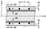
ST7-1.70.10.2 Local Stress Results in Plate and Shell Elements Strand7 reports six components of local stress for plate/shell element results. These components are three direct stresses ((xx, (yy, (zz) and three shear stresses ((xy, (xz, (yz ) or ((xy, (xz,(yz) and as shown in the figure. All six components are available at three layers through the plate thickness, t. These are the -z surface (where z=-t/2), the +z surface (where z=+t/2) and the mid-plane surface (where z=0). For a linear material analysis, the components (xx, (yy, and (xy are calculated... |
|
 2.0 MB |
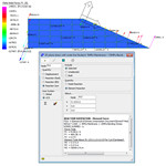
ST7-1.70.10.3 Using the Reinforced Concrete Module Concrete is a widely used construction material with high compressive yet low tensile strengths. Choose Property/Plate RC. The dialog is shown in the following figure: There can be up to four layers of reinforcement bars included and defined for analysis. Simplified (bending only) consists of three basic features: It considers only Moments M as shown in dialog box figure. It considers only the tensioned steel bars located in the tensile part of the concrete section. It uses a rectangular... |
|
| ST7-1.70.20 Results / Extraction | ||
|
0.8 MB |
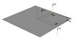
ST7-1.70.20.2 Extracting Forces and Moments from a Plate Mesh This Webnote describes the methods of extracting the total force and moment across a structural cross-section made up of plate elements. Force and moment resultants are very useful quantities for design calculations. For extracting forces and moments from a brick mesh, please refer to ST7-1.70.20.1 Extracting Forces and Moments from a Brick Mesh. The simple cantilever plate mesh shown below (ST7-1.70.20.2 Forces and Moments Simple Plate Mesh.st7) has three force and two moment components applied... |
|
|
0.8 MB |
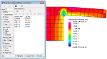
ST7-1.70.20.3 Stress Linearisation using the Peek Tool Geometric discontinuities in structures cause stress concentrations which do not have linear distributions. It is often necessary to calculate equivalent membrane and linear bending stresses from these stress fields to perform compliance checks using design standards. This document illustrates how to post-process 2D plane strain/stress models in Strand7 to extract the linearised membrane and bending stresses along arbitrary lines using the Peek tool. A way to extract the linearised stress is... |
|
|
0.7 MB |
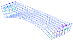
ST7-1.70.20.4 Creating Free Body Diagrams Free body diagrams are a familiar and useful tool with which to examine interactions between sub-components of a model. They allow an engineer to examine the forces on a component of the mesh applied by surrounding elements. In this Webnote we go through the process of creating a free body diagram in Strand7, along with validating the results returned. As an example, we will create a free body diagram of a segment of an arched stone bridge. Free body diagrams require that inter-element forces... |
|
|
1.0 MB |
ST7-1.70.20.9 Extracting Base Shear and Moments from Spectral Response Analysis This Webnote presents procedures for calculating base shear and moment results from spectral response analysis. As these results usually need to be extracted from the summation of reactions at multiple restrained nodes, they cannot be calculated accurately by simply summing the combined peak values. Two methods are demonstrated and the results are compared with reactions calculated from a time history analysis. |
|
|
1.5 MB |
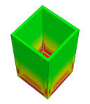
ST7-1.70.20.10 Skin Technique for Stresses on Surfaces of Structural Components This Webnote describes the so-called skin technique and its usage. This technique is sometimes used to obtain more accurate stresses (or strains) on surfaces of structural components which are modelled using 3D solid elements. The technique is useful as a way to improve the accuracy of extrapolated stresses/strains. |
|
| ST7-1.70.30 Results / Display | ||
|
5.0 MB |
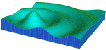
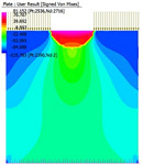
ST7-1.70.30.2 Creating User Defined Result Contours For plate and brick elements, a user defined contour based on stress and strain result quantities can be specified in Results Settings by entering an equation. The equation supports all the Strand7 operators available for general input of data, including conditional operators such as IFPOS and IFPOSB, as described in ST7-1.50.70.10 Assigning Attributes using Equations. In this Webnote, three examples are illustrated: The Signed von Mises stress, SVMS, in 2D can be defined as follows: ... |
|
|
1.6 MB |
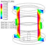
ST7-1.70.30.6 Cutting Plane Contours of Brick Results When a structure is modelled using 3D brick elements, we sometimes need to extract results on a plane that cuts through a group of brick elements. This Webnote discusses contours of brick element results on cutting planes, and their application for calculating moments and forces on a plane. |
|
| ST7-1.70.50 Results / Dynamic | ||
|
0.5 MB |
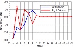
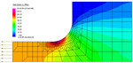
ST7-1.70.50.2 Result Quantities in Spectral Response Mode Superposition This Webnote uses a simple 2D frame to analyse results from the Strand7 spectral response solver. Both modal and combined results are examined. The model being analysed, ST7-1.70.50.2 Result Quantities in Spectral Response Mode Superposition.st7, is shown below. The base of the structure is fully fixed and a horizontal force of 3 kN is applied to one column. Open ST7-1.70.50.2 Result Quantities in Spectral Response Mode Superposition.st7. Run Solver/Natural Frequency, ensuring that at... |
|
| ST7-1.70.60 Results / Combinations | ||
|
1.5 MB |
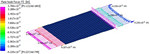
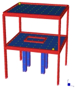
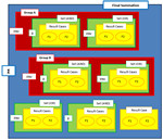
ST7-1.70.60.1 Combining Transient and Static Results Using Envelopes Often, models produce many result cases which need to be combined or filtered to find the worst possible case. The girder bridge shown below has a load path with an AASHTO load template applied. This load path defines moving vehicles on the bridge, which can then be solved for and enveloped. A self-weight load is combined with the moving load in a second envelope. Generate the results to be combined by running both the moving load simulation and a separate linear static analysis. Open ST7-1.70.60.1... |
|
|
3.4 MB |
ST7-1.70.60.4 Combining Harmonic Response and Linear Static Results As the assumption of linearity is inherent in both the linear static and harmonic response solvers, the principle of superposition is applicable to results generated by each. However, because the harmonic response solver may produce an envelope of un-equilibrated results (depending on the method used to combine the modal responses), whilst the linear static solver always produces equilibrated results, the superposition of these two types of solutions is not always straightforward. This Webnote presents two methods of generating results from the combination of static and harmonic loads. |
|
|
1.0 MB |
ST7-1.70.60.6 User Defined Contours Max Function This Webnote examines the procedure of defining a max function contour display in the post-processing environment. The max function described in this Webnote is intended to compare different result components at the same location and result case, for example, to determine the largest stress component at each node. The determination of the maximum value of a single result quantity over multiple result cases can be obtained using the Envelope function described in ST7-1.70.60.2 Envelopes. |
|
| ST7-1.70.70 Results / Validation | ||
|
0.6 MB |
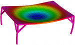
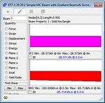
ST7-1.70.70.1 Moment-Curvature Beam with Thermal Gradient Applied When a moment-curvature nonlinear beam is used in conjunction with an applied beam thermal gradient, validating the moment-curvature relationship requires the consideration of the stress-free thermal curvature strain. The beam used in this example is shown below. It has a point load, thermal gradient, and support applied. The support is to stabilise the solution past the point of ultimate moment by providing an alternative load path after perfectly plastic hinging occurs. The total curvature... |
|
|
0.7 MB |
ST7-1.70.70.2 Peek and Contour Results There are a number of different ways to analyse a models results using Strand7. Two popular ones are the results contours (which renders results graphically on the model) and the peek tool (which is commonly used to extract detailed results from a single element). This Webnote outlines the available options associated with each of the tools and the appropriate settings for them to present consistent results. This section outlines the relationship between results on the interior of plates and... |
|
|
1.2 MB |
ST7-1.70.70.6 Mesh Convergence Studies and Stress Singularities The Finite Element Method (FEM) is a way of obtaining an approximate solution to a mathematical representation of a physical system. Because the equations resulting from the mathematical representation are usually too complex for an exact solution to be found, the FEM is normally used to provide solutions that are approximate yet acceptable for practical applications. As the mesh of an FE model is progressively refined, the solution is expected to improve and converge towards the 'exact' solution.... |
|
| ST7-1.70.100 Results / Solvers | ||
|
0.7 MB |
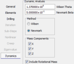
ST7-1.70.100.2 General Solver Defaults This Webnote examines the solver Defaults settings and their uses. The Defaults options typically include various tolerances, factors and limits applicable to certain types of analysis. The default values for these settings are suitable for most model and solver setups and do not generally require modification. In cases where the Defaults require adjustment, it is important to understand what each parameter is, and any potential impact of changing it. |
|
|
0.6 MB |
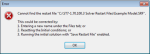
ST7-1.70.100.3 Solver Restart Files This Webnote examines the options and the handling of solver restart files. Three types of solver restart files are available depending on the type of solver considered: Static Restart Files (.SRF), generated by the Nonlinear Static solver; Quasi Static Restart Files (.QRF), generated by the Quasi Static solver; and Dynamic Restart Files (.DRF), generated by the Nonlinear Transient Dynamic solver. |
|
| << Previous (Installation) |